Project Home Rotor MicroController Motor Controller Yaesu G-5500 Software Virtual G-5500 iPoint
The Parallax processor runs off 3.3 volts. Each of the 32 digital I/O lines can source or sink 40 ma. While this is a fairly high current capacity in the digital world it is orders of magnitude lower than required to operate even small stepper motors. The motor used in this project draws 1 Amp. Unlike conventional motors the stepper motor draws approximately the same amount of current no matter what the load. This means that even though the mechanical load is very low the motor still draws maximum current.
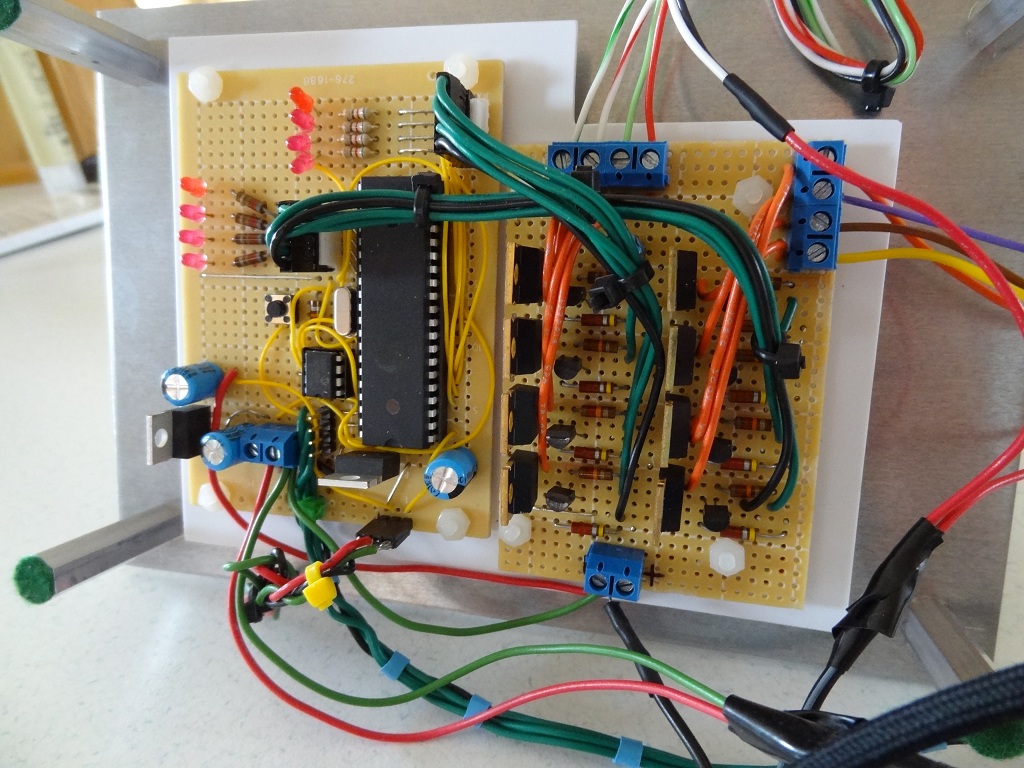
The motor controller is used to amplify the low current output from the processor to the level required by the motor. The power applied to the stepper motor is either on or off so all that is needed is a simple switch. Each unipolar stepper requires one of these switches for each of its four windings. If you look at the picture of the motor controller board in the picture you can see the two banks of four power transistors (one bank for each of the two motors). The green wires you see in the picture carry the output from 8 I/O pins on the processor to the 8 solid state switches on the motor controller board.
For more information on various parts of the project click on the links at the top of the page.